"A" Station Turbine Basement
"A" Station was the first of the "three power stations in one" to be constructed, with work commencing in 1916. The design, prepared by Merz and McLellan prior to the outbreak of World War I, prioritised functionality over architectural aesthetics. The station was initially equipped with five generating units, providing a total capacity of 32 MW.
The building was designed to allow for future expansions. As a result, the walls were clad with corrugated iron sheets upon completion of the first stage of construction.
Babcock and Wilcox were contracted to supply all the steelwork for the buildings, including the boilers.
At the time, Portland cement had to be imported, as local production did not commence until 1929, when Swan Portland Cement Ltd established a plant in Rivervale (an area that is now part of Burswood).
The first stage of construction consisted of two parallel structures sharing a common wall: a turbine hall measuring 46m x 32m, and a boiler house measuring 40m x 21.3m.
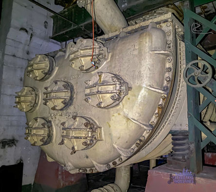
No. 4 Surface Condenser

No.4 Surface Condenser
Surface condensers are a type of steam turbine condensers, commonly used in thermal power stations. They function as heat exchangers, converting exhaust steam from the turbines back into water by transferring its heat to the cooling water. The steam and cooling water remain physically separated by a solid barrier, which allows heat to pass through while preventing the two fluids from mixing.
Built by C. A. Parsons in Newcastle upon Tyne, this cast iron surface condenser was commissioned in 1922 and specifically designed to suit the turbine set and operating conditions of the East Perth Power Station. Surface condensers of this type were characteristic of early 20th-century engineering.
Cooling water entered through the inlet at the bottom right and exited via the outlet at the top left, providing two passes through the steam space (Tweedie, 1994).
In the event of a surface condenser failure, the large automatic relief valve located at the top would release steam directly into the atmosphere, protecting the condenser from overpressure.
Inspection Covers: Bolted covers which provide access to the internal tubes for inspection, cleaning and maintenance.
Bolted Flange Joints: Located along the edges to connect the condenser sections and to ensure a secure, pressure-tight seal.
Shell Body: The main pressure part that houses the condenser tubes and steam space.
(4.2.1 is the plant number allocated to them by Lindsay Tweedie in his 1994 East Perth Power Station Conservation Plan: Volume Three)
References
Tweedie, L (1994). East Perth Power Station Conservation Plan: Volume 3. May 1994

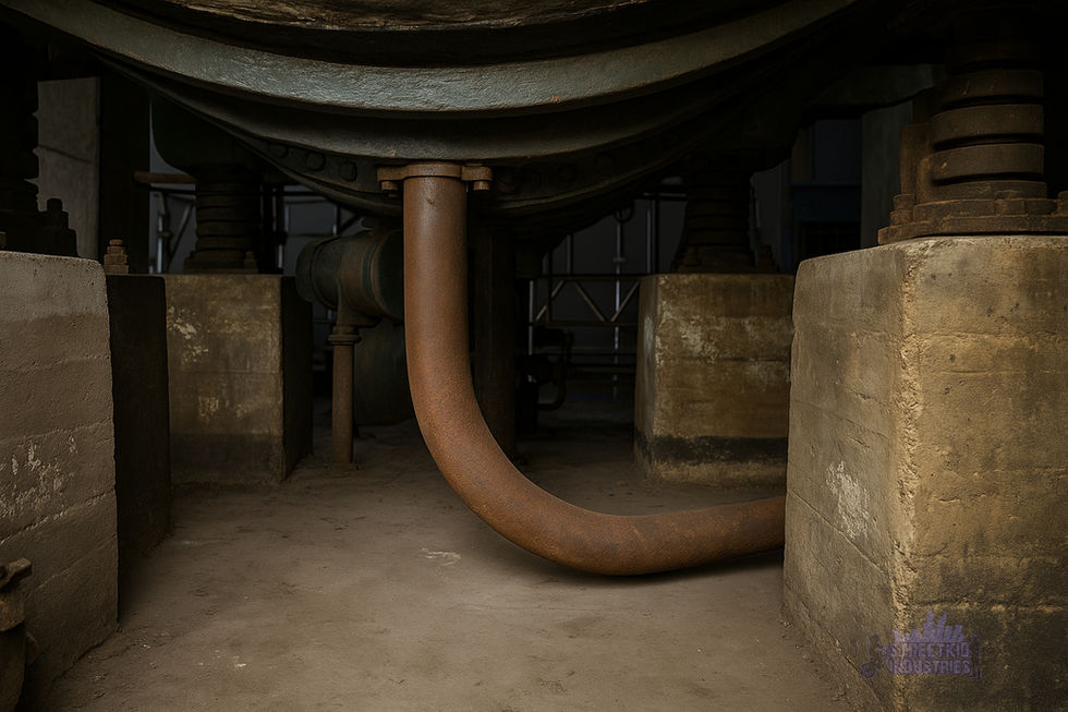
No.4 Lube Oil Coolers

Photo of the A Station Lube Cool Oilers (improved with AI and Photoshop)
The Lube Oil Coolers were manufactured by Serck Radiators Ltd, UK and installed in the turbine basement of 'A' Station around 1922.
To reduce friction and wear, the turbine and generator bearings required a continuous supply of lubricating oil. As the cool oil circulated through the bearings, it absorbed heat generated by the high-speed rotation of the shafts.
The lube oil cooler functioned as a shell-and-tube heat exchanger (a series of tubes inside a large cylindrical shell). Hot oil from the bearings entered the cooler on the tube side, while cooling water from the station’s condenser flowed through the shell side. The water extracted heat from the oil, allowing the cooled oil to be recirculated back into the bearings.
The coolers were located in the basement directly under the turbines to minimise piping layouts. The basement’s cooler temperatures and proximity to the cooling water pipes and pumps helped streamline the heat rejection process.
(4.2.2 is the plant number allocated to them by Lindsay Tweedie in his 1994 East Perth Power Station Conservation Plan: Volume Three)

Photo of the A Station Lube Cool Oilers base (improved with AI)
No.5 Turbine Condenser

Nos. 5 and 6 Surface Condensers
Both Nos. 5 and 6 are twin turbine surface condensers, each comprising of cast iron waterboxes and a riveted steel shell. Cooling water flows inside through hundreds of brass tubes, each about three-quarters of an inch wide. The tubes are held in place by tube plates mounted under the waterboxes. The shell is split horizontally, separating the inlet and outlet waterboxes.
Condenser No. 5 was the first of its kind to use two steam cylinders. It featured a low-pressure dual-flow cylinder, where steam entered through the centre of the waterboxes. Each of the twin cylinders had its own exhaust outlet.
Both were manufactured by C.A. Parson & Co, UK and commissioned in 1928.

No.6 Turbine Condenser


